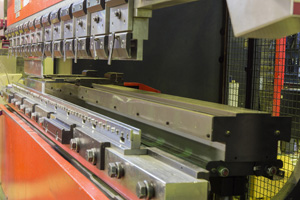
 In backstop gauging, a rotary encoder is used to ensure that the unit to be controlled, such as a machine tool, does not exceed a preset position or direction of travel. Very often, this encoder function is combined with determining the speed of travel of the table, tool head, or similar component. Other sensors may be used for back stop gauging, such as a limit switch or optical sensor; however, properly configured rotary encoders can prove to be more durable and accurate.
Mechanically, both shaft and through bore encoders can be used for backstop gauging, with the preference for one or the other depending on the particular features of the application. EPC's Model TR2 TruTracTM with an integrated pinion gear and rack system is an good candidate for backstop gauging applications.
Electrically, variables such as resolution, output type, channels, voltage, etc, all should be specified to meet the individual application requirements. Due to reciprocating motion, quadrature output is preferred since direction must be determined. Additionally, an index pulse should be specified to ensure the ability to find a home position. Both incremental and absolute encoders are suitable for backstop gauging, with some applications favoring multi-turn absolute feedback due to the ability to determine exact position, even in the event of loss-of-power scenarios.
Environmentally, proximity of the encoder to potential exposure to liquids, fine particulates and extreme temperatures will dictate specification. In applications with wash down requirements, an IP66 or IP67 seal can offer protection against moisture ingress. However, consider a stainless steel or polymer composite housing or shielding the encoder to mitigate the effects of harsh cleaning chemicals and solvents.
Examples: